| Ký hiệu |
Chỉ thị |
Thông số kỹ thuật |
Đơn giá |
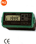
| ĐỒNG HỒ VẠN NĂNG |
| K1009 |
Số |
- DCV: 400V/4/40/400/600v-ACV: 400mV/4/40/400/600v
- Hz: 5,12/51,2/512Hz/5,12/51,2/512kHz/5,12/10MHz
- DCA:400/400µA/40/400mA/4/10A-ACA: 400/400µA/40/400mA/4/10A
- Ω: 400Ω/4/40/400KΩ/4/40Ω - Kiểm tra điốt: 4V/0,4mA
- Kiểm tra tụ: 40nF/400nF/4µF/40µF/100µF
|
1,267,000 |
| K1011 |
Số |
- DCV: 600mV/6/60/600/600V - ACV: 600mV/6/60/600/600V
- Hz: 10/100/1000Hz/10/100/1000kHz/10Hz
- DCA: 600/6000 µA/60/600mA/6/10A - ACA: 600/6000 µA/60/600mA/6/10A
- Ω: 400Ω/4/40/400KΩ/4/40MΩ - Kiểm tra đi ốt 2,8V/0,4mA
- Kiểm tra tụ: 40nF/400nF/4 µF/40 µF/400 µF/4000 µF
- Nhiệt kế: -50,300oC (-58,572oF) –Sử dụng cùng que đo cho 8216
|
1,767,000 |
| K1012 |
Số |
- DCV: 600mV/6/60/600/600V - ACV: 600mV/6/60/600/600V - True RMS.
- Hz: 10/100/1000Hz/10/100/1000kHz/10MHz
- DCA: 600/6000 µA/60/600mA/6/10A - ACA: 600/6000 µA/60/600m A/60/10A
- Ω: 400Ω/4/40/400KΩ/4/40MΩ - Kiểm tra đi ốt: 2,8V/0,4mA
- Kiểm tra tụ: 40nF/400nF/4µF/40µF/400 µF/4000µF
|
2,517,000 |
| K1018 |
Số |
- DCV: 400mV/4/40/400/600V - ACV: 4/40/400/600V
- Hz: 10/100Hz/1/10/100/1000kHz/10MHz -Ω: 400Ω/4/40/400kΩ/4/40MΩ -
- Kiểm tra điốt: 4V/0,4mA – Kiểm tra tụ: 40nF/400nF/4 µF/40 µF/200 µF
|
867,000 |
| K1030 |
Số |
Đồng hồ vạn năng dạng bút điện AC/DCV: 600V; Ω: 40MΩ; C: l00µF; F: 200kHz |
1,467,000 |
| K1051 |
Số |
- DCV/ACV: 600.0mV/6.000/60.00/600.0/1000V. True RMS.
- ACA/DCA: 600.0/6000µA/60.00/440.0mA/10.00A
- Kiểm tra đi ốt; Kiểm tra tụ; tần số; đo nhiệt độ đến 6000C
|
8,500,000 |
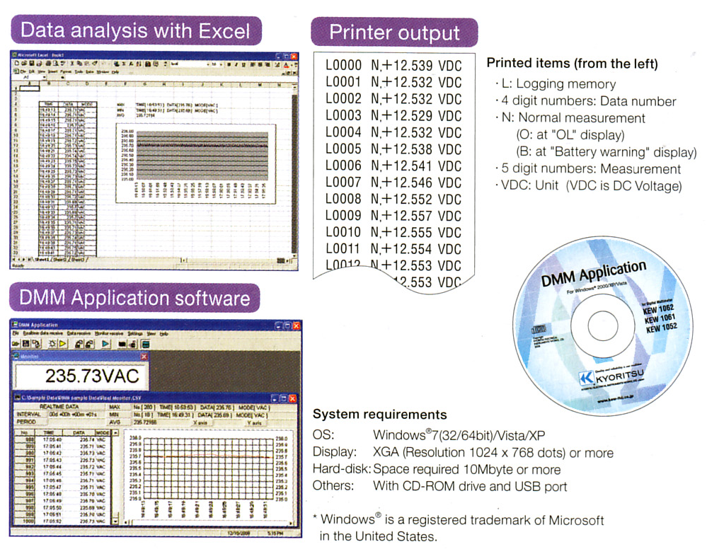
| K1052 |
Số |
Các thông số giống như K1051, có thêm MEAN/RMS (switch). |
10,033,000 |
| K1061 |
Số |
- DCV/ACV: 50.000/500.00/2400.0mV/5.000/50.00/500.0/1000V. RMS.
- ACA/DCA: 500.00/5000.0µA/50.000/500.00mA/10.000A
- Kiểm tra điốt; kiểm tra tụ; tần số; đo nhiệt độ đến 13720C.
|
12,700,000 |
| K1062 |
Số |
Các thông số giống như K1061, co th6m MEAN/RMS (switch). |
14,917,000 |
| K1109S |
Kim |
- DCV: 0.1/0.5/2.5/10/50/250/1000V(20kΩΩ) - ACV: 10/50/250/1000V(9kΩ/V)
- DCA: 50 ΩA/2.5/25/250mA - ACA: 15A-Ω: 2/20KΩ/2/20MΩ
|
983,000 |
| K1110 |
Kim |
- DCV: 0.3(16,7KΩΩ) 3/12/30/120/300/600V(20kΩ/V)
- ACV: 12/30/120/300/600V(9kΩA/) - DCA: 60 µA/30/300mA - Ω: 3/30/300KΩ
- Nhiệt độ: -20,1500C – Sử dụng cùng que đo cho 7060
|
1,650,000 |
| K2000 |
Số |
- ф 6mm - ACA: 60A - DCA: 60A - ACV600V - DCV: 600V - Ω: 34MΩ
- F: 0 ~10kHz(A); 0-300kHZ(V)
|
2,183,000 |
| K2001 |
Số |
- ф10mm - ACA: 100A - DCA: 100A - ACV600V - DCV: 600V - Ω: 34MΩ
- F:0~10kHz(A); 0~300kHZ(V)
|
2,833,000 |
| K2012R |
Số |
- ф10mm - ACA: 120A-DCA: 120A-ACV600V-DCV: 600V-Ω:60MΩ
- F: 0 ~10kHz(A); 0~300kHZ(V) True RMS.
|
3,417,000 |
| MÁY THỬ ĐIỆN ÁP |
| K1700 |
Số |
Bút thử điện áp chỉ thị điện áp bằng đèn led. |
2,050,000 |
| K1710 |
Số |
Bút thử điện áp chỉ thị điện áp bằng màn hiển thị số |
2,567,000 |
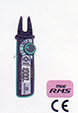
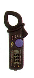
| AMPE KÌM |
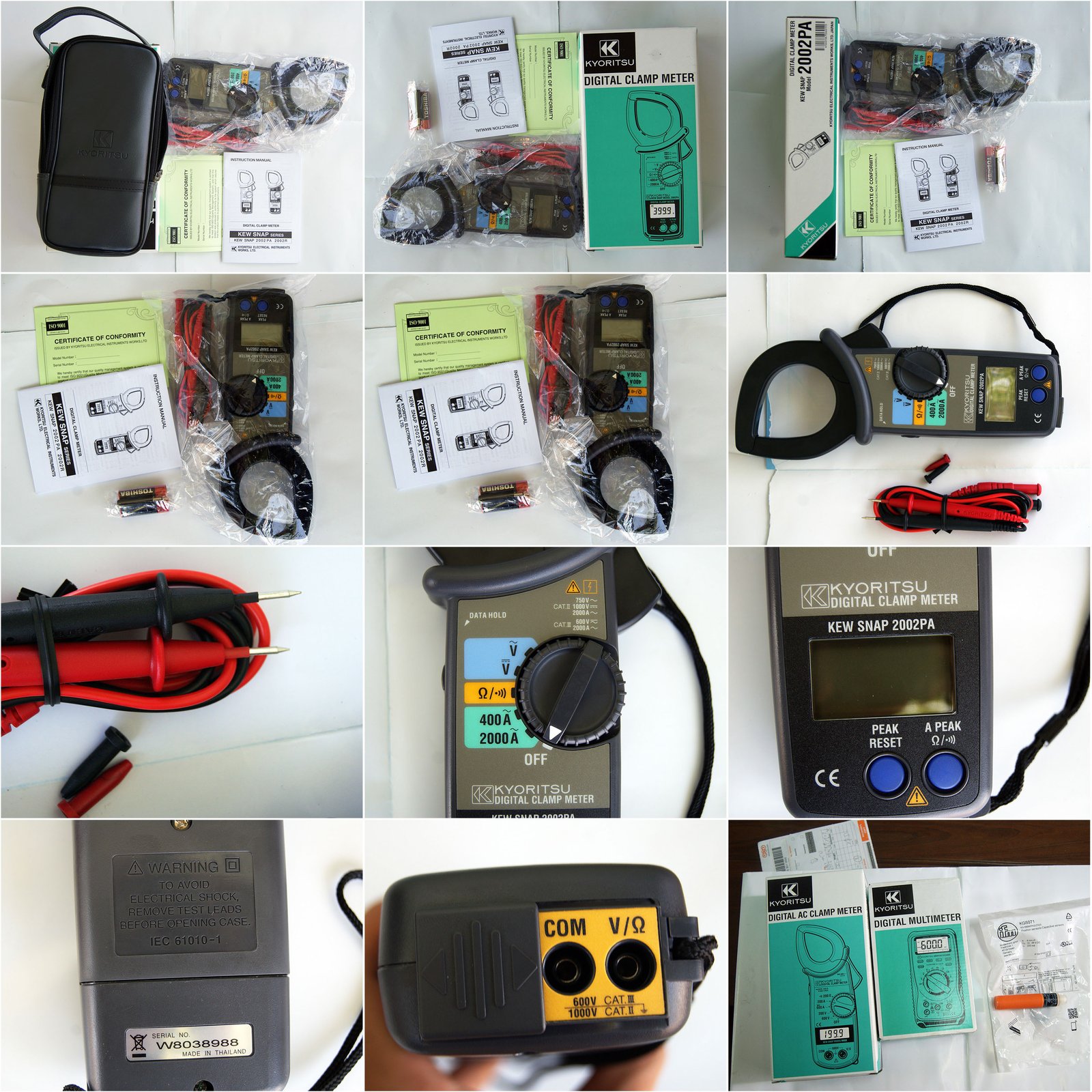
| K2002PA |
Số |
- ф55mm - ACA: 400A/2000A - ACV: 40/400/750V
- DCV: 40/400/1000V - Ω: 400Ω/4k/40k/400kΩ
|
3,300,000 |
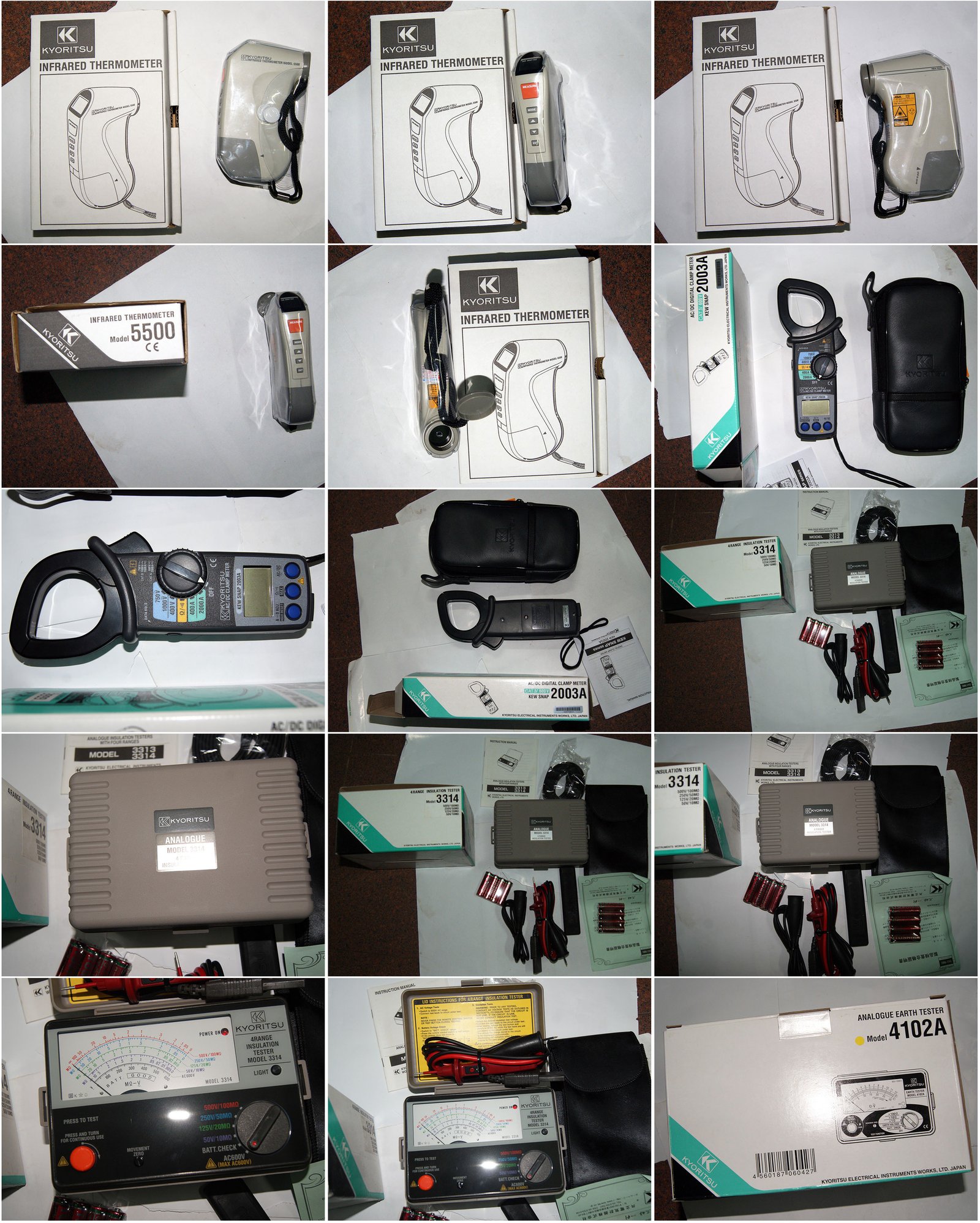
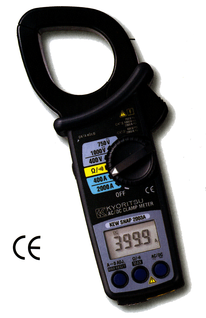
| K2003A |
Số |
- ф55mm - ACA: 400A/2000A - DCA: 400/2000A - ACV: 400V/750V
- DCV: 400/1000V - Ω: 40Ω/4000Ω
|
5,733,000 |
| K2004 |
Số |
ф19mm - ACA: 20/200A - ACV: 500V - DCA: 20/200A-DCV: 200V - Ω: 200Ω |
6,500,000 |
| K2007A |
Số |
ф33mm - ACA: 400A/600A - ACV: 400V/750V - Ω: 400Q/4kΩ |
1,533,000 |
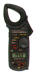
| AMPE KÌM |
| K2009R |
Số |
- ф55mm - ACA: 400A/2000A -DCA: 400A/2000A - ACV: 40/400/750V
- DCV: 40/400/1000V - Ω: 400/4000Ω - F: 10~4000Hz
|
6,267,000 |
| K2017 |
Số |
ф33mm - ACA: 200A/600A - ACV; 200V/600V - Ω: 2000 |
1,533,000 |
| K2031 |
Số |
ф24mm - ACA; 20A/200A |
2,050,000 |
| K2033 |
Số |
ф24mm - ACA: 40A/300A - DCA: 40A/300A |
3,933,000 |
| K2040 |
Số |
ф33mm - ACA: Từ 0 đến 600A; ACV: 6/60/600V; DCV: 600m/6/60/600V; |
2,867,000 |
| K2200 |
Số |
- -Ω:0- 40MΩ
- Ω: Từ 0 đến 60MΩ; F: Từ 0 đến 100kHz;
|
1,350,000 |
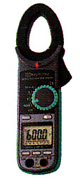
| K2046R |
Số |
- ф33mm - AC/DC A: Từ 0 đến 600A; AC/DC V: Từ 0 đến 600V; True RMS.
- Ω: Từ 0 đến 60MΩ; F : Từ 0 đến 100kHz; C: 40n/400n/ 4µ/40µF
|
4,600,000 |
| K2055 |
Số |
- ф 40mm - AC/DC/A: 0-600A/ 0-1000A; AC/DC V: từ 0 đến 600V;
- Ω: Từ 0 đến 60MΩ ;F:Từ 0 đến 100kHz;
|
4,183,000 |
| K2056R |
Số |
- ф 40mm - AC/DC/A: 0-600A/ 0-1000A; AC/DC V: Từ 0 đến 600V; True RMS.
- Ω: Từ 0 đến 60MΩ; F: Từ 0 đến 100kHz; C: 40n/400n/ 4p/40MF
|
5,183,000 |
| K2300R |
Số |
ф10mm-AC/DC: 0,1/100 A |
2,517,000 |
| K2608A |
Kim |
- DCV: 60V - Ω: 1k/10kΩ |
1,150,000 |
| K2805 |
Kim |
ф35mm - ACA: 6/20/60/200/600A - ACV: 150/300/600V - Ω: 2kO |
1,533,000 |
| KT200 |
Số |
ф30 mm - ACA: 40/400A - ACV: 400/600V - DCV: 400/600V- Q: 400Ω/4KΩ |
917,000 |
| KT203 |
Số |
- ф30 mm - ACA: 40/400A - DCA: 40/400A - ACV: 40Q/600V-
- DCV: 400/6000V - Ω: 400Ω/4000Ω
|
1,967,000 |
| AMPE KÌM DÒNG DÒ |
| K2412 |
Số |
ф40mm - ACA: 20/200mmA/2/20/200/500A. |
11,833,000 |
| K2413F |
Số |
ф68mm - ACA: 200mmA/2/20/200/1000A. |
11,833,000 |
| K2413R |
Số |
Thông số kỹ thuật giống K2413F; Có thêm chức năng RMS. |
12,750,000 |
| K2431 |
Số |
ф24mm - ACA: 20mA/200mA/200A |
6,833,000 |
| K2432 |
Số |
ф40mm - ACA: 4mA/40mA/100A |
9,467,000 |
| K2433 |
Số |
ф40mm - ACA: 40mA/400mA/400A |
7,533,000 |
| K2434 |
Số |
ф28mm - ACA: 400mA/4mA/100A |
6,267,000 |
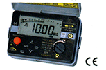
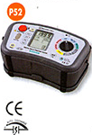
| MÊGÔMÉT |
| K3001B |
Số |
Điện áp thử: 500V/1000V - Phạm vi đo: 2M/20M/200MΩ |
5,767,000 |
| K3005A |
Số |
Điện áp thử: 250V/500V/1000V- Phạm vi đo: 20M/200M/200MQ - ACV: 600V |
5,933,000 |
| K3007A |
Số |
Điện áp thử: 250V/500V/1000V- Phạm vi đo; 20M/200M/2000MQ - ACV: 600V |
7,167,000 |
| K3021 |
Số |
Điện áp thử 125V/250V/500V/1000V- Phạm vi đo: 200M/2000M(S- AQ!DC: 600V |
8,2.83,000 |
| K3022 |
Số |
Điện áp thử 50V/1000V/250V/500V- Phạm vi đo: 200M/2000MQ- AC/DC: 600V |
8,283,000 |
| K3023 |
Số |
Điện áp thử - 100V/250V/500V/1000V- Phạm vi đo: 200M/2000MQ- AC/DC: 600V |
8,283,000 |
| K3121A |
Kim |
Điện áp thử: 2500V - Phạm vi đo: 2GQ/100GΩ |
9,483,000 |
| K3122A |
Kim |
Điện áp thử: 5000V - Phạm vi đo: 5GD/200GΩ |
9,950,000 |
| K3123A |
Kim |
- Điện áp thử: 5000V - Phạm vi đo: 5GQ/200GΩ
- Điện áp thử:10000V - Phạm vi đo: 10GQ/400GΩ
|
13,400,000 |
| K3124 |
Kim |
Điện áp thử: Tự chỉnh từ 1kV đến 10kV - Phạm vi đo: 100MΩ/1.6GΩ/100GΩ. |
34,550,000 |
| K3125 |
Số |
Điện áp thử: 500V/1000V/2500V/50ΩΩ - Phạm vi đo: 1000M/10G/100G/1TΩ. |
17,800,000 |
| K3126 |
Số |
|
41,350,000 |
| K3127 |
|
Điện áp thử: 250V/ 500V/1000V/2500V/5000V -Phạm vi đo: 100G/1k.5/510TΩ. |
63,833,000 |
| K3128 |
Số |
Phạm vi do: 500G/1/2.5/5/35TΩ. |
135,667,000 |
| K3131A |
Kim |
Điện áp thử: 250V/500V/1000V- Phạm vi đo: 100M/200M/40ΩMO - 0:2Ω/20Ω |
5,450,000 |
| K3132A |
Kim |
- Điện áp thử: 250V/500V/1000V- Phạm vi đo: 100M/200M/400MΩ
- Ω: 3Q/500Q-ACV: 600V
|
3,833,000 |
| K3146 |
Kim |
Điện áp thử: 50V/125V - Phạm vi đo: 20M/50MΩ; AC V: 300V |
6,833,000 |
| K3161A |
Kim |
Điện áp thử: 15V/ 50V - Phạm vi đo: 10M/100MΩ; AC V: 600V |
7,833,000 |
| K3165 |
Kim |
Điện áp thử: 500V - Phạm vi đo: 1000MΩ - ACV: 600V |
2,283,000 |
| MÊGÔMÉT |
| K3166 |
Kim |
Điện áp thử: 1000V - Pham vi do: 2000MΩ - ACV: 600V |
2,283,000 |
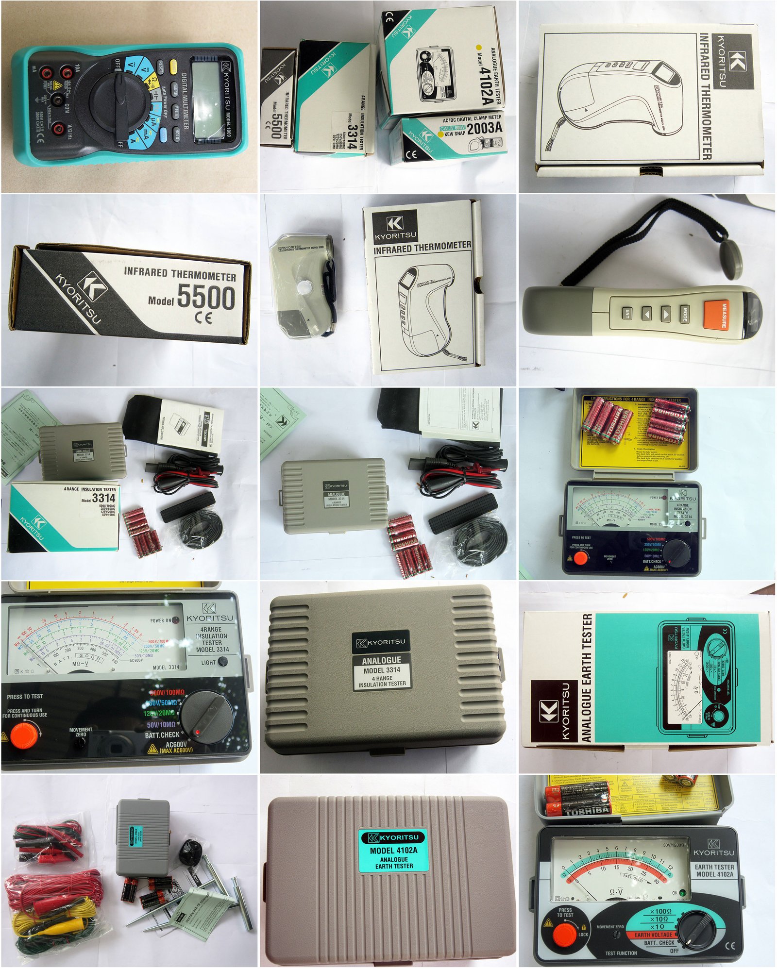
| K3315 |
Kim |
Điện áp thử: 125V/ 250V /500V /1000V - Phạm vi đo: 20MΩ/500/100MΩ/2000M. |
8,183,000 |
| K3321A |
Kim |
Điện áp thử: 250V/500V/1000V – Phạm vi đo: 50M/100M/2000MΩ; ACV: 600V |
7,450,000 |
| K3322 |
Kim |
Điện áp thử: 125V/250V/500V – Phạm vi đo: 20M/50M/100MΩ; ACV: 600V |
8,083,000 |
| K3323 |
Kim |
Điện áp thử: 25V/50V/100V – Phạm vi đo: 10M/10M/20MΩ; ACV: 600V |
8,083,000 |
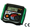
| THIẾT BỊ ĐO ĐIỆN TRỞ ĐẤT |
| K4102A |
Kim |
Điện trở đất: 12Ω/120Ω/1200Ω - Điện áp đất: 30V AC |
5,183,000 |
| K4102AH |
Kim |
Điện trở đất: 12Ω/120Ω/1200Ω - Điện áp đất: 30V AC |
5,633,000 |
| K4105A |
Số |
Điện trở đất 20Ω/200Ω/2000Ω - Điện áp đất: 200V AC |
5,533,000 |
| K4105AH |
Số |
Điện trở đất : 20Ω/200Ω/2000Ω - Điện áp đất: 200V AC |
5,683,000 |
| K4106 |
Số |
2Ω/20Ω/200Ω/2000Ω - 20: Ω/200: Ω |
39,050,000 |
| K4200 |
Số |
Ampekim đo điện trở đất; Phạm vi đo: 20/200/12000; ACA: 100m/1000m/10/30A. |
23,317,000 |
| THIẾT BỊ TỰ GHI DÒNG DÒ |
| K5001 |
Số |
100mA/1000mA; 1.0%-4.0% rdg±2.5%fs |
10,400,000 |
| K5010 |
Số |
Range:100.0mA; ±2.0%rdg±0.9%f.s ~ ±3.5%rdg±2.2%f+sAccuracy of Sensor |
10,050,000 |
| K5020 |
Số |
Range:100.0mA; ±2.0%rdg±0.9%f.s ~ ±3.5%rdg±2.2%f+sAccuracy of Sensor |
12,550,000 |
| THIẾT BỊ ĐO CƯỜNG ĐỘ ÁNH SÁNG |
| K5201 |
Số |
Phạm vi đo từ 0 đến 20.000 Lux. 3 tháng đo tự động |
19,750,000 |
| K5202 |
Số |
Phạm vi đo: 0,1~20.000 LUX |
5,800,000 |
| THIẾT BỊ ĐO DÒNG DƯ |
| K5402D |
Số |
5/10/30/100/300/500mA |
5,167,000 |
| K5406A |
Số |
10/20/30/200/300/500mA |
6,667,000 |
| THIẾT BỊ ĐO NHIỆT ĐỘ TỪ XA |
| K5510 |
Số |
Pham vi đo: -400C ~3000C |
5,983,000 |
| THIẾT BỊ ĐO ĐA NĂNG |
| K6010A |
Số |
Phạm vi đo: 20/2000Ω;25A(20Ω range) 15mA(2000Ω range); 500V DC-570V DC |
10,333,000 |
| K6010B |
Số |
Phạm vi đo: 20/200MΩ /: 20/2000Ω; 500/1000V |
14,500,000 |
| K6011A |
Số |
Phạm vi đo: 20/200/200MΩ /: 20/200MΩ; 250/500/1000V DC |
18,917,000 |
| K6017 |
Kim |
Phạm vi đo: 125V/250V/500V; 20M/50M/100MΩ |
13,917,000 |
| K6018 |
Kim |
Phạm vi đo: 250V/500V/1000V; 50M/100M/2000 MΩ |
13,917,000 |
| K6020 |
Số |
Test Voltage 125V/250V 250V/500V1000V |
40,533,000 |
| K6050 |
Số |
20/200/20000; (LOOP 200/2000Ω, PSC 200A100 ~440V) |
12,583,000 |


.png)


.png)
.png)
.png)
.png)


.png)
.png)
.png)
.png)
.png)


.png)
.png)
.png)
.png)
.png)
.png)
.png)
.png)
.png)
.png)
.png)
.png)
.png)
.png)
.png)
.png)
.png)
.png)
.png)
.png)
.png)
.png)
.png)
.png)
.png)
.png)
.png)
.png)
.png)
.png)
.png)
.png)
.png)
.png)
.png)
.png)
.png)
.png)
.png)
.png)
.png)
.png)
.png)
.png)
.png)
.png)
.png)
.png)
.png)
.png)
.png)
.png)
.png)
.png)
.png)
.png)
.png)
.png)
.png)
.png)
.png)
.png)
.png)
.png)
.png)
.png)
.png)


.png)
.png)
.png)
.png)
.png)
.png)
.png)
.png)
.png)
.png)
.png)
.png)
.png)
.png)
.png)
.png)
.png)
.png)
.png)
.png)
.png)
.png)
.png)
.png)
.png)
.png)
.png)
.png)
.png)
.png)
.png)
.png)
.png)
.png)
.png)
.png)
.png)
.png)
.png)
.png)
.png)
.png)
.png)
.png)
.png)
.png)
.png)
.png)
.png)
.png)
.png)
.png)
.png)
.png)
.png)
.png)
.png)
.png)
.png)
.png)
.png)
.png)
.png)

.png)
.png)
.png)
.png)
.png)
.png)
.png)
.png)

.png)
.png)
.png)
.png)
.png)
.png)
.png)
.png)
.png)
.png)
.png)
.png)
.png)
.png)
.png)
.png)
.png)
.png)
.png)
.png)
.png)
.png)
.png)
.png)
.png)
.png)
.png)
.png)
.png)
.png)
.png)
.png)
.png)
.png)
.png)
.png)
.png)
.png)
.png)
.png)
.png)
.png)
.png)
.png)
.png)
.png)
.png)
.png)
.png)
.png)
.png)
.png)
.png)

.png)
.png)
.png)
.png)
.png)
.png)
.png)
.png)
.png)
.png)
.png)
.png)
.png)
.png)
.png)
.png)
.png)
.png)
.png)
.png)
.png)
.png)
.png)
.png)
.png)
.png)
.png)
.png)
.png)
.png)
.png) photo:3021
photo:3021.png) photo : 3123A
photo : 3123A.png)
.png)
.png)
.png)
.png)
.png)
.png)
.png)
.png)
.png)
.png)
.png)
.png)
.png)
.png)
.png)
.png)
.png)
.png)
.png)
.png)
.png)
.png)
.png)
.png)
.png)
.png)
.png)
.png)
.png)
.png)
.png)
.png)
.png)
.png)
.png)
.png)
.png)
.png)
.png)
.png)
.png)
.png)
.png)
.png)
.png)
.png)
.png)
.png)
.png)
.png)
.png)
.png)
.png)
.png)
.png)
.png)
.png)
.png)
.png)
.png)
.png)
.png)
.png)
.png)
.png)
.png)
.png)

.png)


.png)

.png)
.png)
.png)
.png)
.png)
.png)
.png)
.png)
.png)
.png)
.png)
.png)
.png)
.png)
.png)
.png)
.png)
.png)
.png)
.png)
.png)
.png)
.png)
.png)
.png)
.png)
.png)
.png)
.png)
.png)
.png)
.png)
.png)
.png)
.png)
.png)
.png)
.png)
.png)
.png)
.png)
.png)
.png)
.png)
.png)
.png)
.png)
.png)
.png)
.png)
.png)
.png)
.png)
.png)
.png)
.png)
.png)
.png)
.png)
.png)
.png)
.png)
.png)
.png)
.png)
.png)
.png)
.png)
.png)
.png)
.png)
.png)
.png)
.png)
.png)
.png)
.png)
.png)
.png)
.png)
.png)
.png)
.png)
.png)
.png)
.png)
.png)
.png)
.png)
.png)
.png)
.png)
.png)
.png)
.png)
.png)
.png)
.png)
.png)
.png)
.png)
.png)
.png)
.png)
.png)
.png)
.png)
.png)
.png)
.png)
.png)
.png)
.png)
.png)
.png)
.png)
.png)
.png)
.png)
.png)
.png)
.png)
.png)
.png)
.png)
.png)
.png)
.png)
.png)
.png)
.png)
.png)
.png)
.png)
.png)
.png)
.png)
.png)
.png)
.png)
.png)
.png)
.png)
.png)
.png)
.png)
.png)
.png)
.png)
.png)
.png)
.png)
.png)
.png)
.png)
.png)
.png)
.png)
.png)
.png)
.png)
.png)
.png)
.png)
.png)
.png)
.png)
.png)
.png)
.png)
.png)
.png)
.png)
.png)
.png)
.png)
.png)
.png)
.png)
.png)
.png)
.png)
.png)
.png)